 Oil and Gas Chemical Sampling Quill
Description
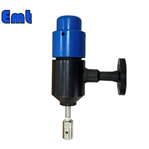
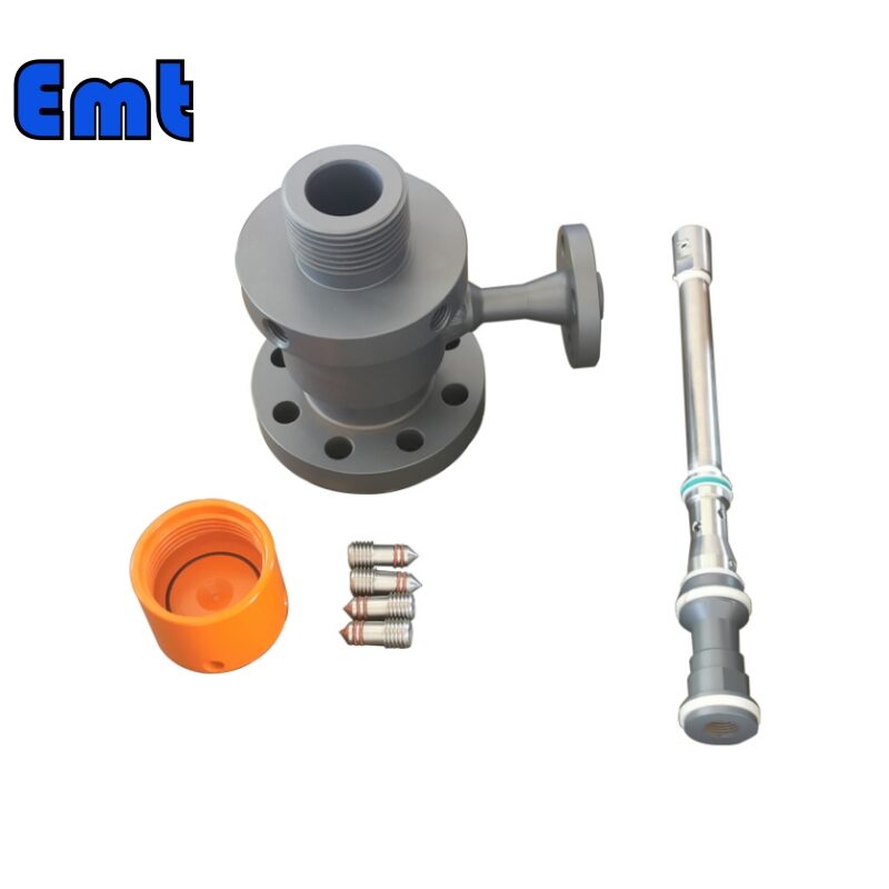
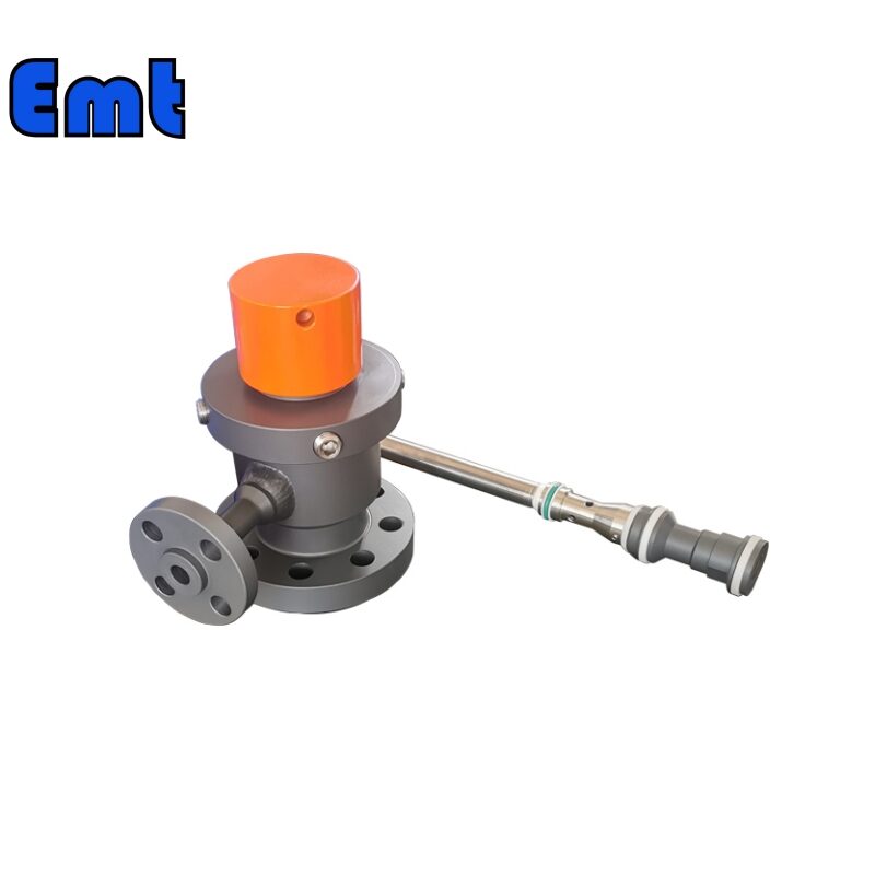
Typically, operators use an Injection Assembly in conjunction with High-Pressure Access Systems. The system comprises an Access Fitting body with a side Tee through which fluid transfer occurs. You can either thread or weld the Tee. When welded, the Tee can be either flanged or buttweld nipples. Threaded Tees, on the other hand, require an NPT-tapped hole on the fitting body. The Tee size is determined based on the injection rate and the viscosity of the injected chemical.
Parameters
| Name | Pipeline Flanged Injection Quill |
| Material | Stainless Steel 304、Stainless Steel 316、DSS F51、Carbon Steel A105N、Inconel 625 |
| Operating Temperature | -20±120 |
| Feature | 1. Easy Operating |
| 2. High Accuracy Long Life | |
| 3. High Efficiency, Low cost | |
| Payment | TT/LC |
| Advantage | Firstly, they are lightweight and flexible. |
| Secondly, nice Injection efficiency. | |
| At last, accurate location tracking. |
Selection Model of Flanged Injection Quill
| Model | |||||||||||||||||||||||||||
| SI | Flanged Injection Quill | ||||||||||||||||||||||||||
| -Code | Plug | ||||||||||||||||||||||||||
| Pxxx | Type | Material | Sealing Material | ||||||||||||||||||||||||
| 0 | No Request | 0 | CS | 0 | No Request | ||||||||||||||||||||||
| 1 | Hollow Plug Body | 1 | 316SS | 3 | DSS | 1 | Viton O-Ring / PTFE Primary Packing | ||||||||||||||||||||
| 2 | Solid Plug Body | 2 | 316LSS | 4 | INCONEL | 2 | HNBR | ||||||||||||||||||||
| – Code | Injection Nut | ||||||||||||||||||||||||||
| Nxx | Connection Size | Material | |||||||||||||||||||||||||
| 0 | i.e. No Request | 0 | i.e. CS | ||||||||||||||||||||||||
| 1 | i.e. 1/4″ | 1 | i.e. 316SS | 3 | i.e. DSS | ||||||||||||||||||||||
| 2 | i.e. 1/2″ | 2 | i.e. 316LSS | 4 | i.e. INCONEL | ||||||||||||||||||||||
| – Code | Injection Tube | ||||||||||||||||||||||||||
| Sxxx-Lx″ | Connection Size | Material | Nozzle | Line size(x″) | |||||||||||||||||||||||
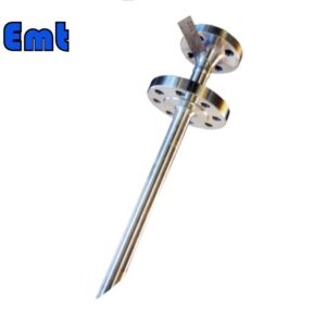
| 0 | No Request | 0 | CS | 0 | i.e. No Request | The most effective position for injection is generally at the center of the pipe | |||||||||||||||||||||
| 1 | i.e. 1/4″ | 1 | i.e. 316SS | 1 | i.e. Open | ||||||||||||||||||||||
| 2 | i.e. 1/2″ | 2 | i.e. 316LSS | 2 | i.e. Quill | ||||||||||||||||||||||
| 3 | i.e. DSS | 3 | i.e. Cap & Core | ||||||||||||||||||||||||
| 4 | i.e. INCONEL | ||||||||||||||||||||||||||
| – Code | Nipple and Valve(or end Flange)of Tee | ||||||||||||||||||||||||||
| Txx | Connection Size | Material | |||||||||||||||||||||||||
| 0 | i.e. No Request | 0 | i.e. CS | ||||||||||||||||||||||||
| 1 | i.e. 1/4″Nipple | a | i.e. 1/4″Nipple and Valve | 1 | i.e. 316SS | ||||||||||||||||||||||
| 2 | i.e. 1/2″Nipple | b | i.e. 1/2″Nipple and Valve | 2 | i.e. 316LSS | ||||||||||||||||||||||
| 3 | i.e. 3/4″Nipple | c | i.e. 3/4″Nipple and Valve | 3 | i.e. D SS | ||||||||||||||||||||||
| 4 | i.e. 1″Nipple | d | i.e. 1″Nipple and Valve | 4 | i.e. INCONEL | ||||||||||||||||||||||
| 5 | i.e. 1/4″Flange | e | i.e. 1/4″Nipple end Flange | ||||||||||||||||||||||||
| 6 | i.e. 1/2″Flange | f | i.e. 1/2″Nipple end Flange | ||||||||||||||||||||||||
| 7 | i.e. 3/4″Flange | g | i.e. 3/4″Nipple end Flange | ||||||||||||||||||||||||
| 8 | i.e. 1″Flange | h | i.e. 1″Nipple end Flange | ||||||||||||||||||||||||
| For Example, SI-P221-N12-S122-L4″-T22 | |||||||||||||||||||||||||||
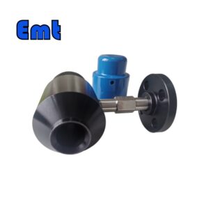
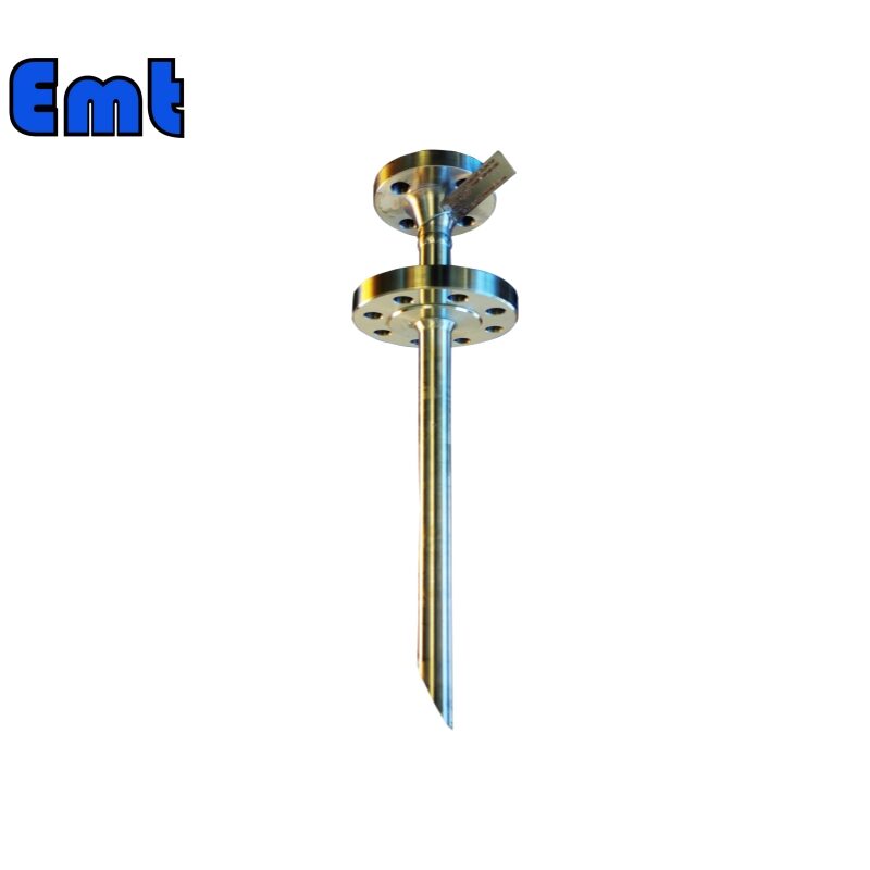
The Flange Connection of Flanged Injection Quill
The Flanged Injection Quill can fit inside an inch diameter schedule 40 flanged additive port. The injector flange is to be sandwiched between an additive port flange and a drilled & tapped blind flange with 1/8” Teflon gaskets.
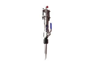
Construction: Flanged Injection Quill assembly shall come complete with injector assembly, flange gaskets, and appropriate fittings. The manufacturer constructs the solution tube from an appropriate material, and it is long. The design of the injector should allow for easy insertion and withdrawal without binding or bending of the diffuser. All wetted components must be compatible with the chemical services.
The direct injection into the pipeline‘s core ensures that the reagents do not gather around the sides. This can cause pipework corrosion and degradation and also lessens the effective contact with the substrate. This, in turn, enhances the durability and efficiency of the chemical reagents infused directly into the pipeline with the use of a dosing pump.
Injection quills are space-efficient and their careful design guarantees a practical and cost-effective method. They increase the lifespan of installed pipework and improve the efficiency of chemical reagents dosed directly inline.
Reviews
There are no reviews yet.