 Pipeline Cleaning Pigs
Description
Oil and gas pipelines are affected by the quality of their pipes, transportation medium, laying environment, and management design. Therefore, corrosion of the pipeline is inevitable. Furthermore, this increases the risk of oil and gas leaks. Oil and gas leakage will bring great harm to the human body, environment, and economy. If you’re worried about your pipe’s corrosion, then contact us! Our EMT Chemical Injection Quill can help you inject inhibitors into the pipe and prevent the pipe from corrosion.
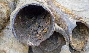
Pipeline Corrosion
There are two main forms of pipeline corrosion: internal corrosion and external corrosion. Pipeline material, transportation medium, environment, management, and design are all key factors that cause pipeline corrosion.
Pipeline quality factors:
Today’s oil and gas transportation mostly uses steel as pipeline materials. The steel pipe is subjected to the electrochemical, chemical and physical effects of the surrounding environmental medium. These effections will cause pipe corrosion.
Transport medium factors:
The oil and gas medium transported often contains water vapor, SO2, H2S and CO2. These react to form compounds that can clog pipes. So this leads to further corrosion of the pipe.
Environmental factors:
Usually, oil and gas pipelines are laid underground. The outer surface of the pipe is covered with soil. The soil contains water, stray currents, and various salts. And there are microorganisms and bacteria inside the soil. Therefore it will lead to chemical corrosion and electrochemical corrosion of oil and gas pipelines. The process of oil and gas transportation is often accompanied by stress. Stress induced fluctuations caused corrosion and minor ruptures of pipes. Prolonged expansion can lead to the formation of large fractures. The erosion of oil and gas in the pipe and rain outside the pipe will cause the metal surface of the pipe to be exposed continuously, resulting in corrosion.
Management design factors:
insufficient professional level of management personnel and pipeline loading and unloading, placement and construction do not comply with the rules will lead to pipeline corrosion.
Pipeline anti-corrosion
After introducing the pipe corrosion, let’s talk about how to protect the pipe from corrosion. Our EMT company focuses on the problem and researches out series of chemical injection quills for pipe protection. Different kinds of products have different effects. Furthermore, custom special requirements are available in our company.
Corrosion inhibitors through the physical adsorption and chemical adsorption of polar groups on the molecule or the combination of both on the pipeline surface form a protective layer to slow down corrosion.
Physical adsorption characteristics: the adsorption speed is relatively fast and has certain reversibility.
Chemical adsorption characteristics: unlike physical ones, this adsorption capacity is strong, irreversible, slow.
Oil and gas pipeline corrosion inhibitors are mainly imidazolines, amines, organophosphates, morines, alkynols, including N, P, S and O heterocyclic compounds.
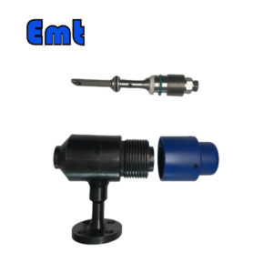
EMT Chemical Injection Quill Specifications
| Category | Details |
| Product Information | |
| Product Name | EMT Chemical Injection Quill |
| Brand Name | EMT Pigging |
| Condition | New |
| Type | Injection & Sampling System |
| Certification | ISO 9001 |
| Warranty | 1.5 years |
| Place of Origin | Liaoning, China |
| Physical Specifications | |
| Weight (KG) | 5 |
| Package Size (cm) | 35 x 40 x 60 |
| Gross Weight (Package, kg) | 8 |
| Material and Construction | |
| Sealing Material | Fluororubber |
| Solid Plug Assembly | 316L Stainless Steel |
| Injection Tube | 316L Stainless Steel |
| NPT Nozzle | 316L Stainless Steel |
| Flange Material | ASTM A105N |
| Operational Parameters | |
| Working Temperature (°C) | -20 to 200 |
| Operation Temperature (°C) | -20 to 150 |
| Working Pressure (LB) | 150LB, 300LB, 600LB, 900LB, 1500LB |
| Pressure Rating (PSI) | 6000 PSI or as per Flange Size |

Other Services of EMT Chemical Injection Quill
| Applications & Industries | |
| Applicable Industries | Building Material Shops, Construction Works, Energy & Mining, Pipeline Pigging, Oil & Gas Pipeline |
| Application | Pipeline Testing |
| Quality and Compliance | |
| Video Outgoing-Inspection | Provided |
| Machinery Test Report | Provided |
| Showroom Location | None |
| Mounting Options | |
| Mounting Types | 2″ Flange, 2″ Flareweld Access Fitting, 1″ Nipple to NPT Ball Valve |
Selection Model of The Injection Quill
According to the selection model, you can choose the specific needs of the product. Like different types, different materials different nozzles, and so on. If you have any other requirements or problems, you can contact our team at info@emtpigging.com. We not only have the best sales team but also own a special technical team. They will help you always.
Model | |||||||||||||||||||||||||||
| SI | Chemical Injector Quill | ||||||||||||||||||||||||||
| -Code | Plug | ||||||||||||||||||||||||||
| Pxxx | Type | Material | Sealing Material | ||||||||||||||||||||||||
| 0 | No Request | 0 | CS | 0 | No Request | ||||||||||||||||||||||
| 1 | Hollow Plug Body | 1 | 316SS | 3 | DSS | 1 | Viton O-Ring / PTFE Primary Packing | ||||||||||||||||||||
| 2 | Solid Plug Body | 2 | 316LSS | 4 | INCONEL | 2 | HNBR | ||||||||||||||||||||
| – Code | Injection Nut | ||||||||||||||||||||||||||
| Nxx | Connection Size | Material | |||||||||||||||||||||||||
| 0 | i.e. No Request | 0 | i.e. CS | ||||||||||||||||||||||||
| 1 | i.e. 1/4″ | 1 | i.e. 316SS | 3 | i.e. DSS | ||||||||||||||||||||||
| 2 | i.e. 1/2″ | 2 | i.e. 316LSS | 4 | i.e. INCONEL | ||||||||||||||||||||||
| – Code | Injection Tube | ||||||||||||||||||||||||||
| Sxxx-Lx″ | Connection Size | Material | Nozzle | Line size(x″) | |||||||||||||||||||||||
| 0 | No Request | 0 | CS | 0 | i.e. No Request | The most effective position for injection is generally at the center of the pipe | |||||||||||||||||||||
| 1 | i.e. 1/4″ | 1 | i.e. 316SS | 1 | i.e. Open | ||||||||||||||||||||||
| 2 | i.e. 1/2″ | 2 | i.e. 316LSS | 2 | i.e. Quill | ||||||||||||||||||||||
| 3 | i.e. DSS | 3 | i.e. Cap & Core | ||||||||||||||||||||||||
| 4 | i.e. INCONEL | ||||||||||||||||||||||||||
| – Code | Nipple and Valve(or end Flange)of Tee | ||||||||||||||||||||||||||
| Txx | Connection Size | Material | |||||||||||||||||||||||||
| 0 | i.e. No Request | 0 | i.e. CS | ||||||||||||||||||||||||
| 1 | i.e. 1/4″Nipple | a | i.e. 1/4″Nipple and Valve | 1 | i.e. 316SS | ||||||||||||||||||||||
| 2 | i.e. 1/2″Nipple | b | i.e. 1/2″Nipple and Valve | 2 | i.e. 316LSS | ||||||||||||||||||||||
| 3 | i.e. 3/4″Nipple | c | i.e. 3/4″Nipple and Valve | 3 | i.e. D SS | ||||||||||||||||||||||
| 4 | i.e. 1″Nipple | d | i.e. 1″Nipple and Valve | 4 | i.e. INCONEL | ||||||||||||||||||||||
| 5 | i.e. 1/4″Flange | e | i.e. 1/4″Nipple end Flange | ||||||||||||||||||||||||
| 6 | i.e. 1/2″Flange | f | i.e. 1/2″Nipple end Flange | ||||||||||||||||||||||||
| 7 | i.e. 3/4″Flange | g | i.e. 3/4″Nipple end Flange | ||||||||||||||||||||||||
| 8 | i.e. 1″Flange | h | i.e. 1″Nipple end Flange | ||||||||||||||||||||||||
| For Example, SI-P221-N12-S122-L4″-T22 | |||||||||||||||||||||||||||
| SI:e.g. Sampling & Injection Assembly, | |||||||||||||||||||||||||||
| P221: e.g. Solid Plug Body in 316LSS Viton O-Ring and PTFE Primary Packing, | |||||||||||||||||||||||||||
| N12:e.g. injection Nut Connection Size is 1/4″and Material is 316LSS, | |||||||||||||||||||||||||||
| S122:e.g. injection Tube Connection Size is 1/4″ and Material is 316LSS. The type of nozzle is quills | |||||||||||||||||||||||||||
| L4″:For 4″pipe. | |||||||||||||||||||||||||||
| T22: Nipple of Tee Connection Size is 1/2″, Nipple material is 316LSS | |||||||||||||||||||||||||||
_032003200_4429.jpg)
Reviews
There are no reviews yet.