
Description
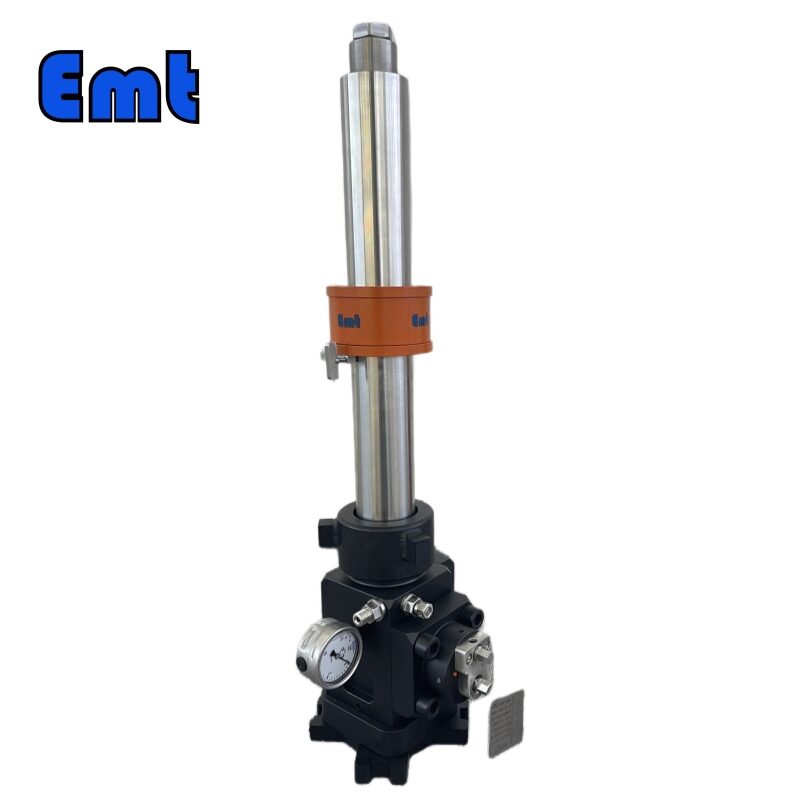
Service Valve Illustration
The service valve is one of the core components of the hydraulic lifting and releasing system, which is an important pressure bearing component in the entire system. The specific form is shown in Figure 4
-241x300.png)
Figure 4
① Service valve operating handle
② Service valve end thread
③ Service valve needle valve
④ Service valve connecting nut
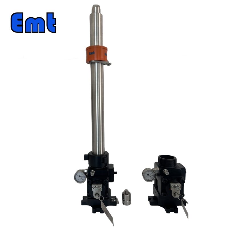
Steps for Using Hydraulic Retriever Tool and Manual Hydraulic Pumps
I. Take out the hydraulic retrieval tool, manual hydraulic pump, and high-pressure hose from the packaging box. Lay them flat on the ground. Next, check for surface damage on all items. Rotate the hydraulic retrieval tool’s connect nut to ensure it rotates smoothly. Confirm the internal thread is undamaged and won’t affect the connection. Check that the O-ring at the bottom of the tool is intact. Also, check the hydraulic oil level in the pump is 5-8mm from the oil filling port. Add oil if necessary.
II. Connect the high-pressure hose to the hydraulic retrieval tool and manual pump. Follow the hydraulic inlet and outlet markings on both tools.
III. Open the valve stem of the retrieval tool. Close the loading valve on the pump. Open the oil filling cover to ventilate the pump. Turn the directional valve on the pump to the installation position. Press until the retrieval tool’s connecting rod is fully exposed. If the pressing handle feels elastic, the air is in the system. Discharge the air by operating the handle 3-6 times.
IV. After completing steps III and IV, turn the directional valve to the position shown in Figure 3. Press until the pressure gauge shows 5MPa. Observe the retrieval tool’s connecting rod. If it retracts into the housing, the tool works normally. Turn the directional valve to the middle position to continue operation. If the connecting rod does not retract, the tool needs repair. Turn the valve to the middle position to relieve pressure. Send the tool to the manufacturer for repair.
V. After completing step IV, open the loading valve to release pressure. Loosen the high-pressure hose connectors on both the retrieval tool and pump. Carefully lift the hose.
Precautions for using Hydraulic Retriever Tool and manual hydraulic pumps
I. Try to open and close the valve stem and pressure relief valve on the Hydraulic Retriever Tool before use, and confirm that the valve stem and pressure relief valve can be opened and closed normally.
II. Before use, try to open and close the load valve and directional valve on the hydraulic pump. Confirm that the load valve and directional valve are working properly.
III. High-pressure hoses shall not be hard-folded to prevent internal damage to the high-pressure pipes after repeated folding.
- During the hydraulic pump pressurization process, pay attention to observing whether there is any oil leakage at the joints of the high-pressure hose. If there is an oil leakage, replace the quick connector at the oil leakage point.
- The manual hydraulic pump equipped with this product is a specialized tool produced by a professional manufacturer. We recommend using hydraulic oil grades 32-46, and grades 22-32 at low temperatures. To prevent injury to operators, please note the following:
- Do not exceed the pump’s maximum working pressure.
- Return the system pressure to zero when refueling.
- Ensure the fuel tank is not overfilled. The hydraulic oil level should be 8mm below the oil cap opening. Overfilling can cause the tank to overflow and lead to injury.
- Keep the load under the operator’s control at all times.
- Do not connect the pump to another hydraulic system pump.
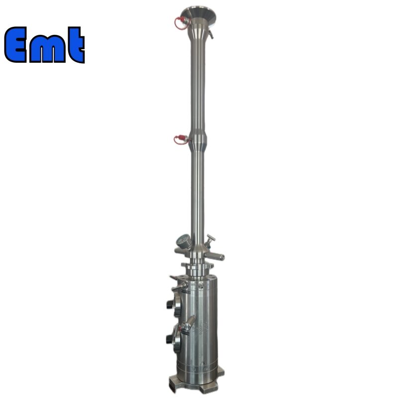
-267x300.png)
Figure 5
Connection method between service valve and base
①Service valve
②Press in base
③ Pipeline
When carrying out the removal operation, before removing the plug, check and confirm whether the service valve operating handle in Figure 4 is in an open state, and also check whether the pressure relief needle valve in Figure 4 is in a closed state. When placing homework. Before placing the plug, check and confirm that the service valve operating handle in Figure 4 is in the open state, and at the same time, check and confirm that the pressure relief needle valve in Figure 4 is in the closed state.
Precautions for using a Service Valve with double isolation
I. First, for all rotating and friction parts of service valves, use good lubricating grease for maintenance. Use in moderation, not too much. Replace defective parts strictly to prevent accidents.
II. Then the valve ball core is the core component of the service valve. If the valve ball core is damaged, it will cause the maintenance valve to fail or close loosely. Do not scratch the spool surface under any circumstances.
III. After that, if you damage the external hexagonal screw on the service valve, replace it with high-strength screws of the same specification.
IV. Finally, our company has pre-assembled and debugged the service valves. Do not disassemble or assemble them without authorization. Our company will not bear any consequences arising from unauthorized disassembly and assembly.
Important Safety Information for Using Hydraulic Retriever Tool
This manual provides technical information on operating the EMT Double Acting Hydraulic Retriever. It is not intended to instruct the purchaser or user on the correct removal of probes in a pressurized system. The procedures for probe removal included here are for illustrative purposes only.
Specific removal procedures must be developed by the tool owner or operator for each application. As a minimum, these procedures must address the safety of the tool operator and the technical effect on the operating system. Additionally, compare the Approved Probe Removal Procedures with the illustrative examples in this Hydraulic Retriever Operation Manual to ensure there are no conflicts.
Do only use tools made of materials that will not produce sparks when used such as tools with plastic or brass surfaces!
When operating retrieval tools, use approved personal safety tools like glasses, and gloves. helmet, shoes, etc.!
Reviews
There are no reviews yet.