
Description
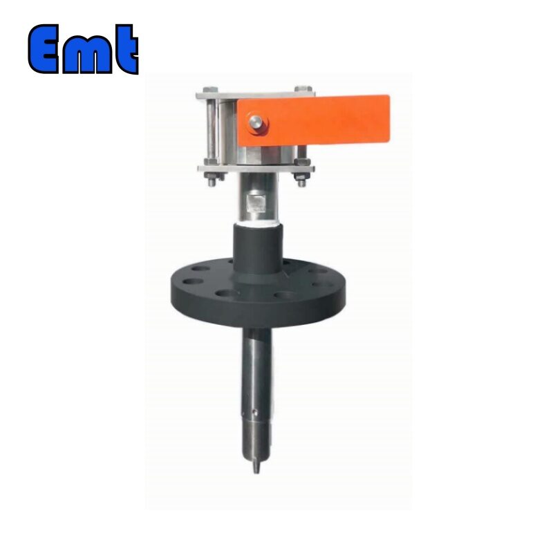
The EMT Flanged Injection Quill is a specialized device designed for the safe and precise injection of chemicals into a pipeline or process system. This equipment is essential in various industrial processes, particularly in sectors like oil and gas, water treatment, and chemical processing. An injection quill is a precision device used for injecting chemicals into pressurized systems such as pipelines or vessels. Here’s a concise overview of its key features and applications:
Key Features of EMT Flanged Injection Quill
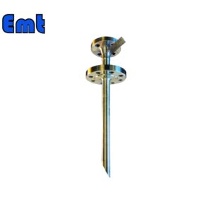
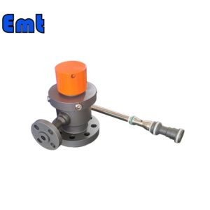
The quill connects to the pipeline via a flanged interface, ensuring a robust and leak-proof attachment suitable for high-pressure environments. Additionally, the quill is typically made from stainless steel, which resists corrosive chemicals and high temperatures, thus ensuring durability and a long service life. Moreover, it facilitates accurate chemical dosing, reducing waste and promoting optimal mixing at the pipeline’s center. Furthermore, features in the quill prevent backflow and ensure safe chemical delivery into the pipeline without external exposure.
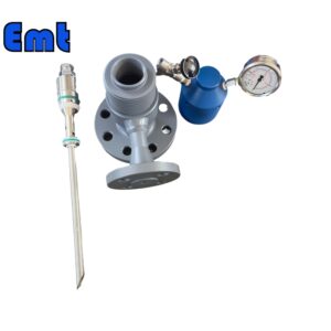
By injecting directly into the flow stream, the quill ensures fast and even mixing, critical for process effectiveness. The check valve boosts safety by blocking any reverse flow into the chemical system. Injection quills adapt well across various industries, handling different pressures and chemical interactions efficiently.
Specifications
| Name | Pipeline Chemical Injection Quill Sampling System |
| Material | Stainless Steel 304、Stainless Steel 316、DSS F51、Carbon Steel A105N、Inconel 625 |
| Operating Temperature | -20±120 |
| Feature | 1. Easy Operating |
| 2. High Accuracy Long Life | |
| 3. High Efficiency, Low cost | |
| Payment | TT/LC |
| Advantage | Firstly, they are lightweight and flexible. |
| Secondly, nice Injection efficiency. | |
| At last, accurate location tracking. |
Applications of Flanged Injection Quill
Corrosion Control: Injects inhibitors directly into pipelines to prevent internal corrosion.
Water Treatment: Adds precise amounts of disinfectants or coagulants to water systems.
Process Optimization: Enhances reaction outcomes in chemical processing by ensuring precise chemical dosing.
Scale Prevention: Delivers scale inhibitors into systems where mineral scale buildup is a concern, such as in boilers and cooling towers.
The EMT Flanged Injection Quill is a critical component for maintaining system integrity, enhancing safety, and optimizing chemical usage in industrial processes. Its robust design and precise functionality make it a valuable tool for a wide range of industrial applications.
In water treatment, injection quills help in dosing chemicals like coagulants and disinfectants precisely. They are also vital in oil and gas for injecting corrosion inhibitors and biocides to maintain pipeline integrity. In chemical processing, quills provide exact amounts of reactants for consistent and controlled reactions.
Overall, the injection quill is essential in industries where exact chemical dosing is necessary to maintain system efficiency and ensure safety.
Components:
The body of an injection quill is typically made from materials like stainless steel or PVC, suitable for the chemicals and environment. A nozzle extends into the vessel or pipeline, ensuring direct delivery of chemicals into the flow stream. A check valve is integral to the design, preventing process fluid from flowing back into the chemical feed line. Depending on the installation, the connection fittings might be threaded or flanged.
Functionality:
The quill’s nozzle protrudes into the flow stream, allowing for direct chemical injection at the center of the flow. This placement is crucial for effective dispersion. A metering pump usually works in conjunction with the quill to control the volume of chemical injected. This setup ensures precise dosing and minimizes waste.
Selection Model of EMT Flanged Injection Quill
| Model | |||||||||||||||||||||||||||
| SI | Chemical Injector Quill | ||||||||||||||||||||||||||
| -Code | Plug | ||||||||||||||||||||||||||
| Pxxx | Type | Material | Sealing Material | ||||||||||||||||||||||||
| 0 | No Request | 0 | CS | 0 | No Request | ||||||||||||||||||||||
| 1 | Hollow Plug Body | 1 | 316SS | 3 | DSS | 1 | Viton O-Ring / PTFE Primary Packing | ||||||||||||||||||||
| 2 | Solid Plug Body | 2 | 316LSS | 4 | INCONEL | 2 | HNBR | ||||||||||||||||||||
| – Code | Injection Nut | ||||||||||||||||||||||||||
| Nxx | Connection Size | Material | |||||||||||||||||||||||||
| 0 | i.e. No Request | 0 | i.e. CS | ||||||||||||||||||||||||
| 1 | i.e. 1/4″ | 1 | i.e. 316SS | 3 | i.e. DSS | ||||||||||||||||||||||
| 2 | i.e. 1/2″ | 2 | i.e. 316LSS | 4 | i.e. INCONEL | ||||||||||||||||||||||
| – Code | Injection Tube | ||||||||||||||||||||||||||
| Sxxx-Lx″ | Connection Size | Material | Nozzle | Line size(x″) | |||||||||||||||||||||||
| 0 | No Request | 0 | CS | 0 | i.e. No Request | The most effective position for injection is generally at the center of the pipe | |||||||||||||||||||||
| 1 | i.e. 1/4″ | 1 | i.e. 316SS | 1 | i.e. Open | ||||||||||||||||||||||
| 2 | i.e. 1/2″ | 2 | i.e. 316LSS | 2 | i.e. Quill | ||||||||||||||||||||||
| 3 | i.e. DSS | 3 | i.e. Cap & Core | ||||||||||||||||||||||||
| 4 | i.e. INCONEL | ||||||||||||||||||||||||||
| – Code | Nipple and Valve(or end Flange)of Tee | ||||||||||||||||||||||||||
| Txx | Connection Size | Material | |||||||||||||||||||||||||
| 0 | i.e. No Request | 0 | i.e. CS | ||||||||||||||||||||||||
| 1 | i.e. 1/4″Nipple | a | i.e. 1/4″Nipple and Valve | 1 | i.e. 316SS | ||||||||||||||||||||||
| 2 | i.e. 1/2″Nipple | b | i.e. 1/2″Nipple and Valve | 2 | i.e. 316LSS | ||||||||||||||||||||||
| 3 | i.e. 3/4″Nipple | c | i.e. 3/4″Nipple and Valve | 3 | i.e. D SS | ||||||||||||||||||||||
| 4 | i.e. 1″Nipple | d | i.e. 1″Nipple and Valve | 4 | i.e. INCONEL | ||||||||||||||||||||||
| 5 | i.e. 1/4″Flange | e | i.e. 1/4″Nipple end Flange | ||||||||||||||||||||||||
| 6 | i.e. 1/2″Flange | f | i.e. 1/2″Nipple end Flange | ||||||||||||||||||||||||
| 7 | i.e. 3/4″Flange | g | i.e. 3/4″Nipple end Flange | ||||||||||||||||||||||||
| 8 | i.e. 1″Flange | h | i.e. 1″Nipple end Flange | ||||||||||||||||||||||||
| For Example, SI-P221-N12-S122-L4″-T22 | |||||||||||||||||||||||||||
| SI:e.g. Sampling & Injection Assembly, | |||||||||||||||||||||||||||
| P221: e.g. Solid Plug Body in 316LSS Viton O-Ring and PTFE Primary Packing, | |||||||||||||||||||||||||||
| N12:e.g. injection Nut Connection Size is 1/4″and Material is 316LSS, | |||||||||||||||||||||||||||
| S122:e.g. injection Tube Connection Size is 1/4″ and Material is 316LSS. Type of nozzle is quills | |||||||||||||||||||||||||||
| L4″:For 4″pipe. | |||||||||||||||||||||||||||
| T22: Nipple of Tee Connection Size is 1/2″, Nipple material is 316LSS | |||||||||||||||||||||||||||
_032003200_4429.jpg)


Reviews
There are no reviews yet.