
Description
Double Acting Hydraulic Retriever Overview
The hydraulic retrieval tool, developed and produced by our company, is used to operate pipelines under normal operating conditions. This tool enables safe and convenient installation or retrieval of hanging pieces or probes. Compared with traditional mechanical designs, our hydraulic design can greatly reduce the size and weight of hydraulic retrieval tools. Consequently, it significantly improves portability and reduces the space requirements for product use. Moreover, through innovative design, hydraulic retrieval tools are driven by hydraulic pressure, making operations more convenient and labor-saving. Additionally, the use of replaceable connectors greatly extends the service life of the tools.
Hydraulic retrieval tools, service valve diagram, and main components
Hydraulic retrieval tool system diagram
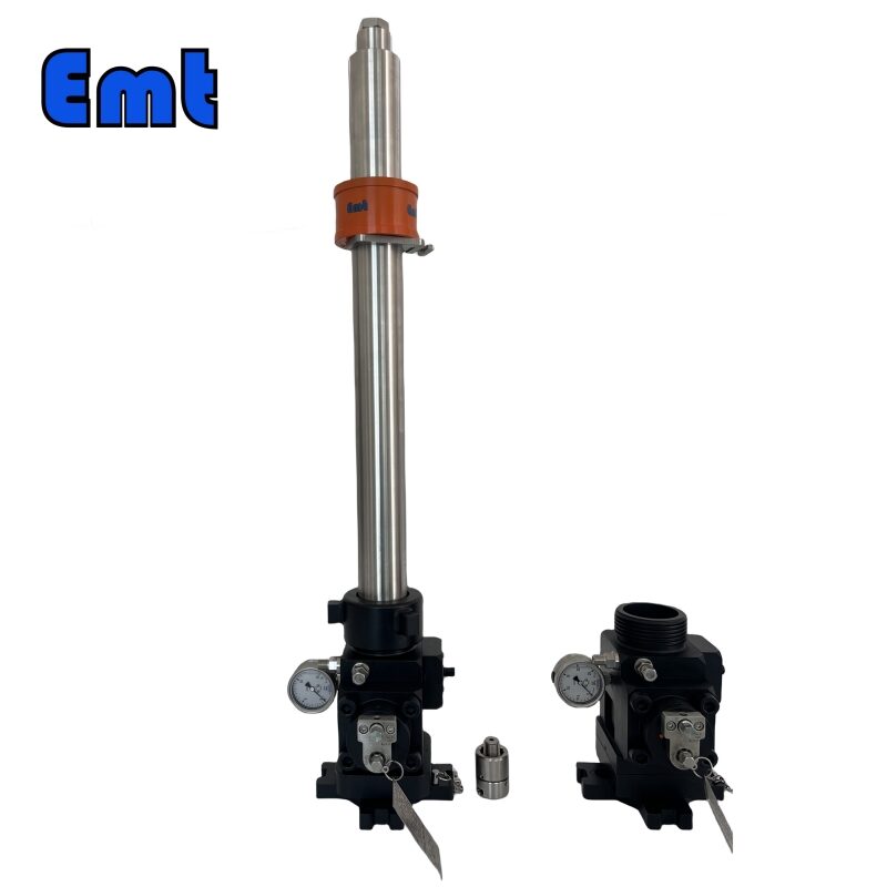
The hydraulic retrieval tool consists of multiple components, as shown in Figure 1
.png)
Figure 1
Hydraulic retrieval tool system diagram
Table 2. Hydraulic retrieval tool system diagram, names of each component
| Item | Name |
| 1 | Service valve connection connecting nut |
| 2 | Service valve operating handle |
| 3 | Hydraulic retrieval tool connecting nut |
| 4 | Hydraulic retrieval tool pressure gauge |
| 5 | Hydraulic retrieval tool relief valve |
| 6 | Hydraulic outlet quick connector |
| 7 | Hydraulic inlet quick connector |
| 8 | Hydraulic retrieval tool valve stem |
| 9 | Manual hydraulic components |
Hydraulic retrieval tool and manual hydraulic pump
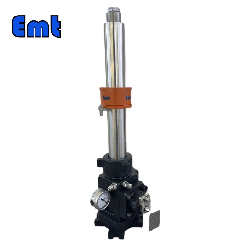
The hydraulic dismantling tool and manual hydraulic pump constitute the core moving parts of the hydraulic lifting and releasing system, which are used for corrosion monitoring hanging, or probe lifting and releasing operations. The hydraulic dismantling tool is shown in Figure 2 below; The schematic diagram of the manual hydraulic pump component is shown in Figure 3.
.png)
Figure 2
Detailed component diagram of hydraulic retrieval tool
① Handwheel
② Hydraulic inlet quick connector
③ Hydraulic outlet quick connector
④ Valve stem
⑤ Hydraulic retrieval tool pressure gauge
⑥ Hydraulic retrieval tool relief valve
⑦ Hydraulic retrieval tool connecting nut
⑧ Hydraulic retrieval tool connecting rod
⑨ Connecting rod thread
.png)
Figure 3
Manual hydraulic pump diagram
① Hydraulic pump pressure gauge
② Hydraulic pump load valve
③Hydraulic outlet quick connector
④ Hydraulic inlet quick connector
⑤ Middle position of directional valve
⑥ Retrieval position of directional valve
⑦ Installation position of directional valve
Steps for using hydraulic retrieval tools and manual hydraulic pumps
- First, take out the hydraulic retrieval tool, manual hydraulic pump, and high-pressure hose from the packaging box. Lay them flat on the ground. Check for surface damage on all items. Rotate the hydraulic retrieval tool’s connect nut to ensure it rotates smoothly and the internal thread is undamaged. Confirm the O-ring at the bottom of the tool is intact. Check that the hydraulic oil level in the pump is 5-8mm from the oil filling port. Add oil if necessary.
- Second, connect the high-pressure hose to the hydraulic retrieval tool and manual pump according to their marked inlets and outlets. Then open the valve stem of the retrieval tool, close the loading valve on the pump, and open the oil filling cover to ventilate the pump. Turn the directional valve on the pump to the installation position, and press until the retrieval tool’s connecting rod is fully exposed. If the pressing handle feels elastic, indicating air in the system, operate the handle 3-6 times to discharge the air.
- Then connect the high-pressure hose to the hydraulic retrieval tool and manual pump according to their marked inlets and outlets. Open the valve stem of the retrieval tool, close the loading valve on the pump, and open the oil filling cover to ventilate the pump. Turn the directional valve on the pump to the installation position, and press until the retrieval tool’s connecting rod is fully exposed. If the pressing handle feels elastic, indicating air in the system, operate the handle 3-6 times to discharge the air.
- Lastly, open the loading valve to release pressure. Loosen the high-pressure hose connectors on the retrieval tool and pump, then carefully lift the hose.
Precautions for using hydraulic retrieval tools and manual hydraulic pumps
First, try to open and close the valve stem and pressure relief valve on the hydraulic retrieval tool before use. Confirm that the valve stem and pressure relief valve can open and close normally.
Second, before use, try to open and close the load valve and directional valve on the hydraulic pump. Confirm that the load valve and directional valve are working properly.
Third, avoid hard folding high-pressure hoses to prevent internal damage from repeated folding.
During the hydraulic pump pressurization process, observe the high-pressure hose joints for oil leakage. If you see oil leakage, replace the quick connector at the leakage point.
The manual hydraulic pump is a specialized tool produced by a professional manufacturer. Use hydraulic oil grades 32-46, and grades 22-32 at low temperatures.
To prevent injury, do not exceed the pump’s maximum working pressure. When refueling, return the system pressure to zero. Ensure the fuel tank’ weight is ok. The recommended hydraulic oil level is 8mm from the oil cap opening. Refueling during use may cause the tank to overflow and result in injury.
Always keep the load under the operator’s control. Never connect the pump to another hydraulic system pump.
Reviews
There are no reviews yet.